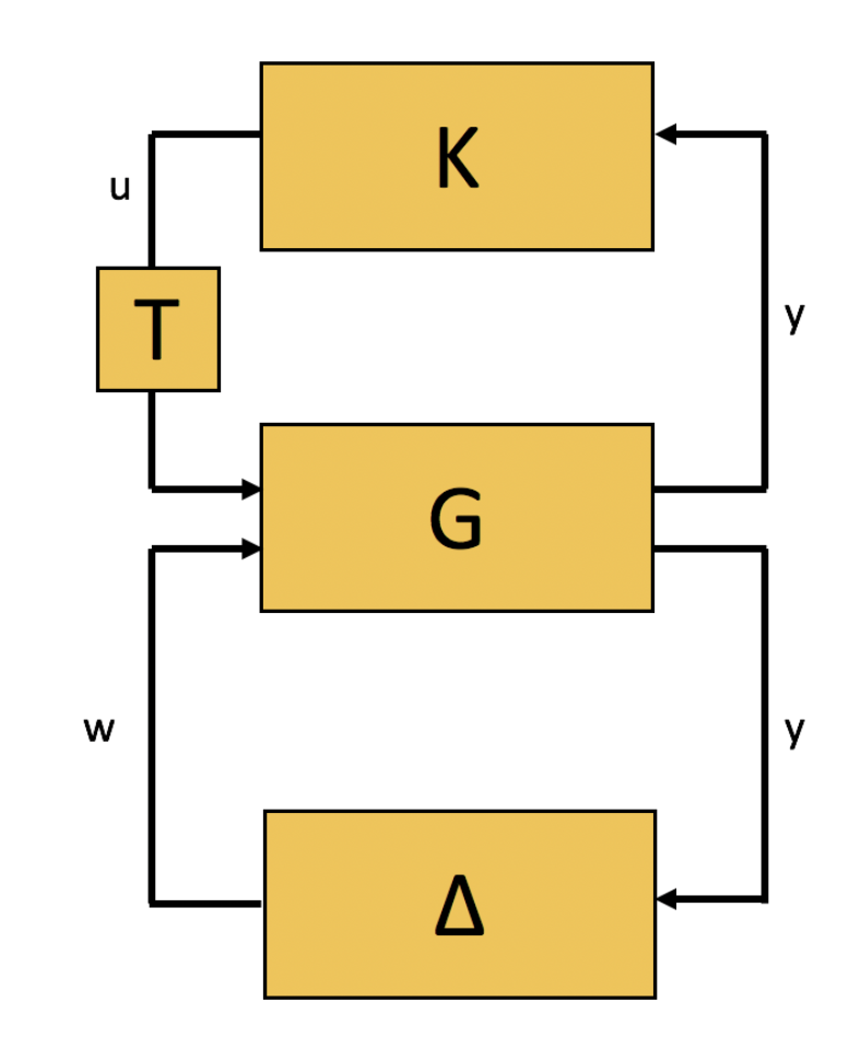
Control theorists describe interconnected systems using a diagrammatic language of blocks and arrows. While control-theoretic block diagrams are rarely ambiguous within the established conventions of the field, they encompass subtleties that might differ from cosmetically similar diagrammatic languages used in other fields. This, adapted from my graduate thesis, is a brief introduction to the diagrammatic language of control theory, emphasizing blocks, implementation, uncertainty, and delay.
In general, a block in a control diagram describes a transfer function. The transfer function \( G \) between an input \( u \) and an output \( y \) is an operation on \( u \), a vector-valued signal through time, that produces \( y \), a vector-valued signal through time.

We can write this mathematically as:
\[ y = G(u) \] Equation 1
Typically, unless otherwise noted, \( G \) is causal, meaning that at any given time, the present value of \( y \) depends only on past values of \( u \) and \( y \); the future does not affect the past.
Because \( G \) can depend on past values of both \( u \) and \( y \), we can describe the internal states \( x \) of \( G \) as a dynamical system with a differential equation with respect to time \( t \). We write \(\dot{x}=\frac{dx}{dt}\).
\[ \begin{aligned} \dot{x} &= f(x,t) + g(x,t)u \\ y &= h(x) \end{aligned} \] Equations 2 and 3
We have now assigned to the simple block in Figure 1 two meanings, expressed as Equation 1 and Equations 2 and 3. These meanings are compatible, but not equivalent. Equation 1 expresses the input-output behavior of the system, while Equations 2 and 3 give us one realization of the input-output behavior. A given realization corresponds to exactly one input-output, but a given input-output can have infinitely many realizations. We make a further distinction between realization and implementation, which is the distinction between a differential equation model of a system and a description of the actual physical system that the differential equation model describes.1
For example, the elementary mathematical operation of addition in Equations 2 and 3 might be implemented as the flows of water in and out of a tank. It might be suitable for some problems to treat addition and subtraction of water as positively and negatively signed values of the same term \( u \). To build the system, or to diagnose problems in the system, it might be necessary to treat addition and subtraction separately. This distinction between realization and implementation is nonstandard even in control theory, and somewhat provisional.
Input-output descriptions are a framework for organizing facts that we already know and highlighting facts that we do not know; they are not models or hypotheses in the typical scientific sense, nor designs in the typical engineering sense. However, in the particular capacity to characterize all possible models, hypotheses, and designs that result from given assumptions and data, input-output descriptions far exceed implementational descriptions, and facilitate the (intuitive or systematic) generation of testable implementational descriptions. It is often useful to characterize one part of a larger system in implementational detail while subsuming other parts of the system into input-output relationships.
Four special types of blocks merit particular attention. One is a controller. Controllers are transfer functions, with at least one corresponding implementation, that are designed by the scientist or engineer to test a hypothesis or achieve an engineering goal. Controllers are contrasted with plants, blocks that represent extant transfer functions in the natural or technological world. The distinction between controller and plant, between what is designed and what is extant, is somewhat arbitrary, depending on the question being asked. A third special type of block that can be interconnected with other blocks is a delay block. While these look the same as any other block, they simply pass a signal forward untransformed after a time delay. Lastly, a special type of block that can be interconnected with other blocks is an uncertainty block. Rather than representing specific transfer functions, uncertainty blocks represent bounded sets of functions; a block diagram with an uncertainty block in it (often expressed as a \( \Delta \)) should be understood to represent several possible functions, rather than just one. This uncertainty-based approach is important when we want to understand whether a model of a system is any good: if our decisions or conclusions about the system are narrowly dependent on the particular parametric assumptions of a single model, we call the model (or system) fragile. If our decisions or conclusions do not depend on particular parametric assumptions, we call the model (or system) robust. In general, even systems that are robust to some assumptions are fragile to others.2
A diagrammatic style that includes uncertainty and delays, spanning input-output and implementation, is a central concern of my recent work, both technically and conceptually. Diagrammatic descriptions are more than cartoons; they are arguments, associated with particular mathematical structures.
